|
and PS/2 devices - v. 1.1 You
are
the visitor n.
Best view with 1024x768 |
||
|
and PS/2 devices - v. 1.1 You
are
the visitor n.
Best view with 1024x768 |
||
 |
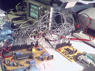 |
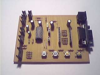
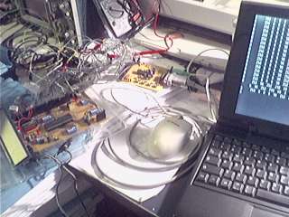
| A PIC 16F877 microcontroller connected to a PS/2 mouse and to a PC; the circuit, on the left in the two images, is a version (v. 2.1) built after the one described on this page, with more TX/RX channels and a few LEDs, and at the moment it is under test; on the oscilloscope, PS/2 data and clock are displayed. |
| Back to Home page | Similar
topics on this site: PIC 16F877 Development Board v. 1.2 PIC - PS/2 mouse interfacing and communication Keypad 4x5 for microcontrollers |
| Circuit's characteristics
On this page a simple circuit is described, allowing to interface a microcontroller to a PS/2 device and to the serial port of a PC, working at RS-232 levels. On the board also four pushbuttons are available, whose logic level can be read by the microcontroller and therefore used as an user input. Concerning the value of protection resistors for the PS/2 connector and for the RS-232/TTL adapter (see schematic further), the circuit have been designed for the PIC 16F877 microcontroller. Being anyway the circuit simple, and resistors' value not critical, it should be suitable also for other PICs and other microcontrollers, too. On this page, we'll refer to the PIC 16F877. The circuit must be fed by a +5 V supply; should the supply be different, the RS-232 interface could work not properly, and the PC serial port and possibly also the microcontroller could be damaged; also the PS/2 mouse could be damaged. The microcontroller and the circuit must be connected to the same supply pins (Vdd = +5 V, GND); should the microcontroller receive a different supply, its ports connected to the circuit could be damaged. For a few informations about communication with a PS/2 mouse, you could have a look at PIC - PS/2 mouse interfacing and communication on this site. Concerning the communication with the RS-232 serial port, the well.known TTL/RS-232 adaper MAX 232 is used. Up to four channels can be used, two as input and two as output. The microcontroller can be interfaced with the 232 serial port with a great freedom, as the nine RS-232 signals are available on two connectors; the four I/O channels of the MAX232 are also available on two connectors; in this way, through simple wires, soldered wires, or wires ending in a connector, up to four TTL ports of the microcontroller can be connected to some of the RS-232 signals.(two as input and two as output). Typically, two channels will be TD and RD; the others two available channels can be used as an instance to manage RTS and CTS, DTR and DSR or DCD, RI. The use of connectors also allows the "simulated" handshake, as an instance connecting DTR to DSR etc..
Acknowledgement and disclaimers PIC and Microchip are registered trademarks. The schematic, the
circuit's layout and all the informations contained in this page are
supplied "as they are", without any form of warranty. I don't assume of
course any direct or indirect responsibility for direct or indirect
damages to things or person coming from informations got from this
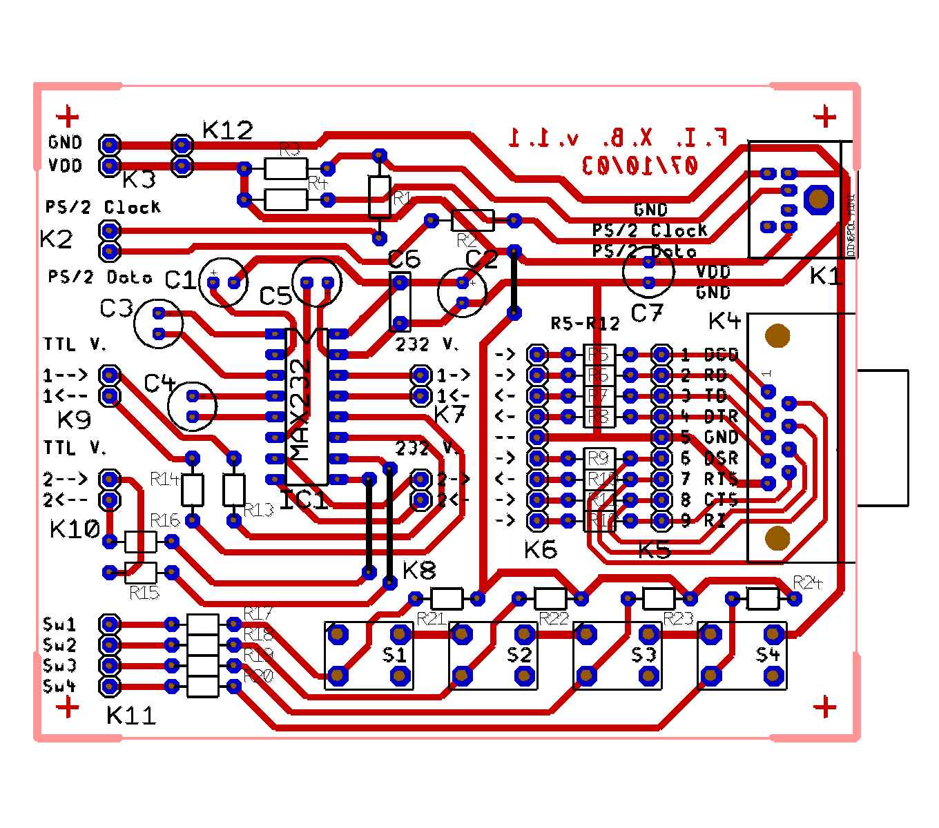
article. In any case, be always aware of what you are doing! The circuit has been designed with TARGET 3001! Light (400 pins license). It's a cheap and in the same time powerful PCB CAD. The circuit Note: the images on this page are low resolution ones (100 dpi). To have the same images, but at 300 dpi, in a new window, where you can print or save them, you can click directly on images on this page or on the links below each one. Further, in the section "Images needed to build the circuit", you can find all together the links to save 300 dpi images. As you can see below here, the nine RS-232 port's signals are available on the K5 connector. The signals' direction are showed by the arrows near connecotrs' pins. Between K5 and K6, 330 Ohm protection resistors are mounted. The signals on K6 you wish to connect to the microcontroller must be connected to the proper pins of K7 and K8 (RS-232 levels); on K9 and K10, connected to the MAX 232 through protection resistors, you find the TTL signals corresponding to those on K7 and K8. The microcontroller should therefore be connected to K9 and K10. The two connectors K5 and K6 allow to make proper wiring for the "simulated" handshake: as an instance,you could connect DTR on K6 to DSR on K6 or K5, so placing between DTR and DSR a 2*330 Ohm resistor in the first case and a 330 Ohm resistor in the second one. Please read further the notes about protection resistors.
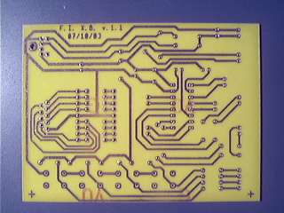
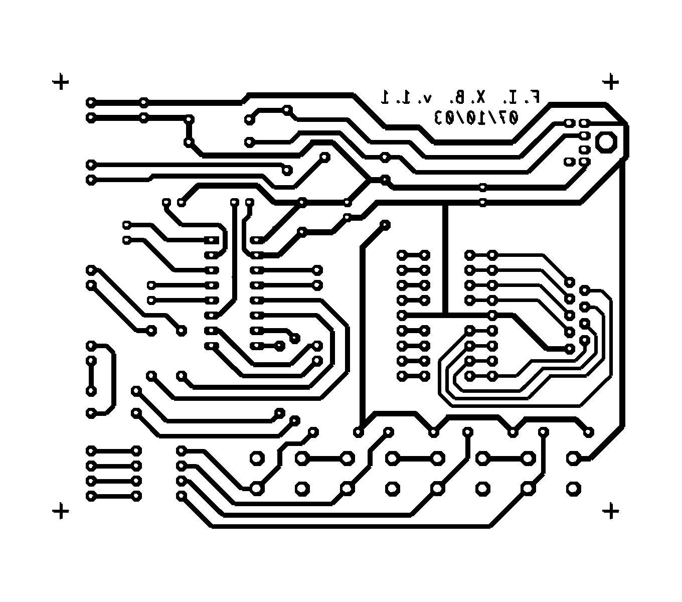
Here components placement and tracks view at 300 dpi The
supply, the same one of the microcontroller, must be connected to the
K3 connector. As previously said, if supply provided to the board is
not the same provided to the microcontroller (the same Vdd and Vss
pins), the microcontroller could be damaged. If supply is not +5 V, the
devices connected, that is the PS/2 mouse and the PC serial port, could
work not properly or even being damaged. The K12 connector allows
supply to be fed to other circuits. On the K2 connector Clock and Data signals for PS/2 communication are available. On the K11 connector the logic levels of the four pushbuttons are available; they are normally high, because of the pull-up; pressing a pushbutton, the related pin is brought to a low logic level. Remarks about protection resistors Protection resistors R1, R2, R13, R14, R15, R16, R17, R18, R19, R20. They limit the current sourced/sunk by microcontroller's ports in case of improper wiring or wrong programming of I/O pins; the maximum current is about 5 V / 330 Ohm = 15 mA. If your microcontroller can't source/sink such a current, you must increment resistors' value. In some microcontrollers, also exist a maximum value of sourced/sunk current for a given set of ports: as an instance, with improper wiring and programming mistakes, having 15 mA sourced/sunk by the up to ten ports that it is possible to connect to this circuit, the maximum current rating could be overcome. Protection resistors R5 to R12. RS-232 electrical specifications set that devices must tolerate a short circuit, and that in such event the current must be limited. Protection resistor R5 to R12, in this case, should not be necessary. For precaution reasons, anyway, I have decided to insert protection resistors, whose value (330 Ohm) must be considered just a starting basis, and not the proper value for every RS-232 port. You should know that, implementing a "simulated" handshake by direct interwiring on the pins of K5 connector, in case you make a mistake, a RS-232 output pin could be connected to ground or to another output pin, therefore realizing a direct connection between something like +15 V and -15 V. In this case, the RS-232 drivers inside the PC should limit the current, but, cautiously, it is better to interwire pins of K6, or interwire pins of K5 and K6. The same for signals to be connected to K7 and K8, which, coming from K6 instead of K5, can pass through protection resistors R5-R12. PLEASE NOTE that the maximum current in case of improper wiring could be about (15 - (-15) ) V / 330 Ohm, that is 90 mA; if the driver limits current (and in this case protection resistors are probably not necessary), there will be no consequences; if the driver does not limits current, the value of 90 mA could be too high for the driver itself. In this case, it is necessary to increase the value of resistors. Protection resistors protects in the same way the MAX 232, too. Please, pay attention: increasing too much the value of resistors R5 - R12 could lead to a wrong reception; the RS-232 standard sets a receiver input impedance between 3 KOhm and 7 KOhm; connecting as an instance DTR and DSR, and using a 3 KOhm protection resistor, voltage on DSR could even arrive at the half of that on DTR, maybe going outside noise margins; in case of improper wiring, anyway, current would be limited to about 30 V / 3 KOhm = 10 mA. It's up to you to chooes the right value depending on the 232 drivers of your PC and on the TTL-232 adapter you mount on the circuit. In order to test possible changes in the waveforms caused by protection resistors, I have converted TD to TTL levels, sent it back to the first TTL input channel connecting together the two pins of K9, and connected to RD the first MAX232 output channel, that is, in short words, to connect TD to RD after two level conversions. Serial communication has been tested in the following conditions: 330 Ohm protection resistors, 115200 bps, TD on K6 connected to K7 (1 <--), pin 1 <-- of K9 (that is, TD converted to TTL levels) connected to 1--> of K9, and 1--> of K7 (that is TD converted back into 232 levels,) connected to RD on K6; the oscilloscope has displayed a small change of the RD waveform, but not enough to leave noise margins, and, testing hundreds/ thousands bytes, exactly what has been transmitted has been received (01010101 B).
Components list Note: all resistors are 5% ones. C1-C2-C5 10µF ELKO2.5-6 50 V
|
|||||
| Images needed to build the circuit
If you wish to build this circuit (after you have read the section "Acknowledgement and disclaimers"), you can find here the links to the images you need (at 300 dpi), images you can anyway view and save in other sections of this page. Components
placement and tracks view at 300
dpi (187 KB) |
| Buon lavoro! |
| Last update: 17 November 2003, 20.40 |
|